Back to basics: PIC is not PC
Microprocessors are good, but don't forget about microcontrollers. Microprocessors are smart but they are flawed - they are too generic, too complex, running too complex code and hence unreliable. Microcontrollers are perfect implementation of KISS. So let's look back to low level - asm, mics, ICs, MCUs, etc.
Over my childhood I was addicted to electronics. Not the music, and not the gadgets. But to soldering, semiconductors, circuits... Then I met PC - and I jumped from hardware to software. Recently I bought Raspberry Pi - and remembered the roots.
The next step was arduino clone - that is self assembled arduino on top of ATmega328P. But that's too simple. I remember though before I jumped to soft - I was going to learn PIC. Finally the time has come. Arduino also proved itself handy - as a PIC programmer.
One note to the above excellent project of Rhys - if you deal with low TTL/CMOS logic it's hard (and dangerous) to be dealing with relatively high voltage of 13.5V. Looking into specs of the lowest grade PIC I bought (PICF629) it's explicitly stated that 13.5V is MAX Vpp. while MIN is Vdd+3.5V. That means - it's sufficient to have additional 3.5-4.5V source - eg. 3xAA - which shouldn't be a surprise for someone dealing with ics. Then just step-up Vpp input from Vdd instead of Gnd to the BJT emitter.
With this - we have PIC burning kit, next install gputils and gpsim - which will be your PIC IDE. And we're ready to flow. Next stupid listing at the bottom is kinda Hellow World1 for PIC - shift register control to move led light across the bar. That's right, PIC doesn't have nifty Arduino Wiring libs so here you code, not play.
The PIC of my choice is as I mentioned maybe the lowest model - at least it was the cheapest in the shop nearby - smth. about 1euro. And for the reason - it does not have any peripherals except timer and comparator. Not even USART. So everything is to be coded manually.
Anyway, once you have asm file you compile it, debug/simulate it, and burn it. First though you may want to ensure programmer is working and dump original config/calibration in case you'd need to erase it
$ ardpicprog -p /dev/ttyUSB0 -o dump.hex --skip-ones
/dev/ttyACM0
Ardpicprog version 0.1.2, Copyright (c) 2012 Southern Storm Pty Ltd.
Ardpicprog comes with ABSOLUTELY NO WARRANTY; for details
type `ardpicprog --warranty'.  This is free software,
and you are welcome to redistribute it under certain conditions;
type `ardpicprog --copying' for details.

Initializing programmer ...
Device pic12f629, program memory: 1024 words, data memory: 128 bytes.
Reading program memory,
reading data memory,
reading id words and fuses,
done.

$ gpasm picShiftOut.asm
$ gpsim picShiftOut.cod
$ ardpicprog -p /dev/ttyUSB0 -i picShiftOut.hex --burn -d pic12f629
/dev/ttyACM0
Ardpicprog version 0.1.2, Copyright (c) 2012 Southern Storm Pty Ltd.
Ardpicprog comes with ABSOLUTELY NO WARRANTY; for details
type `ardpicprog --warranty'.  This is free software,
and you are welcome to redistribute it under certain conditions;
type `ardpicprog --copying' for details.

Initializing programmer ...
Device pic12f629, program memory: 1024 words, data memory: 128 bytes.
Burning program memory, 61 locations,
burning data memory, 0 locations,
burning id words and fuses,Write to device failed
Oops... no idea why it happens but code is there, and it works. You may verify by making dump again and disassembling it with gpdasm.
 |
 |
 |
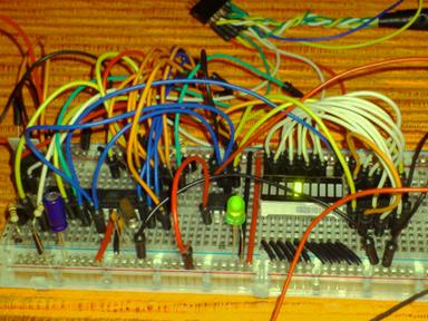
This is how it runs. Here on the picture PIC is behind bigger green LED. It's disconnected from Atmega - Vdd red wire goes straight to rail instead of Atmega leg controlling Vdd. Also behind this red wire is BJT controlling Vpp - programming voltage of +5v of USB and 4.5V of 3xAA. Rightmost is 74HC164 SIPO shift register without latch, wired to led bar. Disregard LM35 thermistor I left here for another ADC probe of ATmega.
And finally the code. It's heavily commented to reflect my understanding of the PIC guts and why I coded it that way and not other. I've used this blank stub to begin with.
    list    p=p12F629, n=0, b=4, r=dec
    processor p12f629
    radix   dec

    include "p12f629.inc"

    errorlevel      -302    ; Don't complain about BANK 1 Registers

    __CONFIG    _MCLRE_OFF & _CP_OFF & _WDT_ON & _INTRC_OSC_NOCLKOUT
    ;__IDLOCS       b'00111110010000' ;ardprog still fails on fuses


            ; globals
                    ; bits on GPIO
pin7        equ     0       ;GP0
pin6        equ     1       ;GP1
pin5        equ     2       ;GP2 and T0CkI
pin4        equ     3       ;GP3 input only
pin3        equ     4       ;GP4
pin2        equ     5       ;GP5

OCLK        equ GP2
ODAT        equ GP1
CBLOCK 0x20
    WCNT, WPRM, MCNT
ENDC

Start   org     0x00;program starts at location 000
        nop
        nop         ;NOPs to get past reset vector address
        nop
        nop
        nop

SetUp   bsf     STATUS, RP0 ;Bank 1
        movlw   0x38        ;This is taken from 0x3FF for this chip
        movwf   OSCCAL      ;Push INTOSC calibration data
        clrwdt              ;Reset watchdog timer >>> WdSleep
        movlw   b'10001110' ;Turn off T0CKI, prescale for WDT to 1:64
        movwf   OPTION_REG  ; that should result to ~1sec sleep time
        movlw   b'00001000' ;Set GP0,1,2,4,5, as output
        movwf   TRISIO      ;enable outputs
        ;movlw  b'00000001' ;Enable TMR1 INT >>> TmSleep
        bcf     STATUS, RP0 ;bank 0
        movlw   b'00000111' ;Set up W to turn off Comparator ports
        movwf   CMCON       ;must be placed in bank 0
        ;movlw  b'00001100' ;Timer1: no PS,
        clrf    GPIO        ;Clear GPIO of junk
        clrwdt              ;And watchdog timer
        goto    MLReset


ShftOut movlw   0x8         ;ShiftOut(WPRM) for 74HC164
        movwf   WCNT        ;Timing in 4MHz RC INTOSC (1MHz Tcy)
        ;bcf    STATUS, RP0 ;we dont really switch to bank1 anywhere around
        rrf     WPRM,F      ;Pre-fetch bit. Just to save time later
loop    btfss   STATUS,C    ;1us : If set skip to nop followed by HIGH
        goto    $+4         ;2us : Jump to data LOW
        nop                 ;3us : align data timings
        bsf     GPIO,ODAT   ;4us : Data is sensed on raised edge
        goto    $+4         ;5us :_/--\__/--\__/-- clocks levels
        bcf     GPIO,ODAT   ;4us :_____/-----\____  data levels
        nop                 ;5us : 0     1     0    data read
        nop                 ;6us : MIN Setup time Tsu is ~ 1/2 of period
        rrf     WPRM,F      ;7us : is time between DAT change and CLK rise
        bsf     GPIO,OCLK   ;8us : Hold time is just 5ns so clocks could be
        bcf     GPIO,OCLK   ;9us : /\____/\____/\__
        decfsz  WCNT,F      ;10us: Check loop condition
        goto    loop        ;11us: and repeat iteration
        return              ;Just in case - we have WRPM restored here
    ;We can sleep in power-down mode with simpe setup through
    ;Watchdog timer (18ms ~ 2s) For lower resolution and wider scale better
    ;use Timer1 with LPOSC/PS (32kHz-4kHz) ~ 30us-16s Timer1 is also more
    ; precise, WDT depends on external conditions like Vdd & Tenv
WdSleep clrwdt              ; WD time set by prescaler at setup hence fairly
        sleep               ; simple code: Clear WD, fall to sleep and return
        return              ; INTs are off, no need to check reason for waking
    ;The beauty of the timer with LP/ASYNC is that it runs independently of
    ;our actions. That is - once we started it, we can spend whatever time
    ;doing other preparations - it will still overflow and INT after Xus.
    ;So we can set, sleep, wake, and if it runs at eg. 4khz - full overflow
    ;will INT at exactly 1/4000*65536=16.384s
    ;You'll need some extra circuitry and 2 pins though -
    ; 32kHz crystal, 2caps, pins2,3. I have only 20MHz crystals at the mmt.
TmSleep nop
        return

Main    movf    MCNT,W      ;Load current
        call    getArr      ; byte from arr to
        movwf   WPRM        ; shift parameter
        call    ShftOut     ;Serialize WPRM
        call    WdSleep     ;Wait
        decfsz  MCNT,F      ;Loop: dec cnt
        goto    Main        ;Loop: Iterate
MLReset movlw   ARRS        ;Loop: Reset
        movwf   MCNT        ; counter
        goto    Main        ;Loop: Start
ARRS    equ 0x8
getArr  addwf   PCL,F
        retlw   00000000b
        retlw   00000001b
        retlw   00000010b
        retlw   00000100b
        retlw   00001000b
        retlw   00010000b
        retlw   00100000b
        retlw   01000000b
        retlw   10000000b
endArr
    if ((getArr & 0xff00 ) != (endArr & 0xff00))
        error "Array may not cross page boundary"
    endif ; Idea found at http://members.shaw.ca/swstuff/lightbar.html
    end
    ; vim: ts=4 noet sts=4 ai:
Link...
Sat Nov 2 21:51:36 2013
Upd.: Sun Nov 3 16:18:53 2013